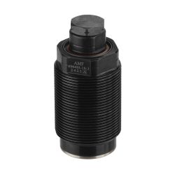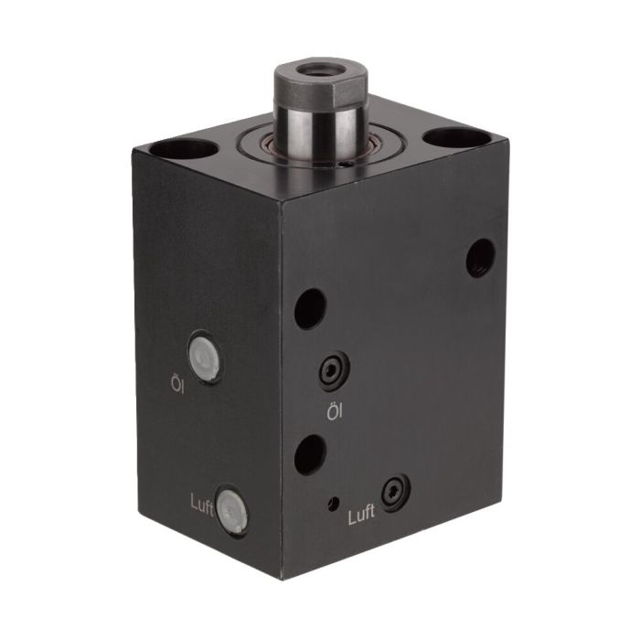
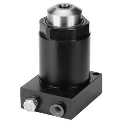
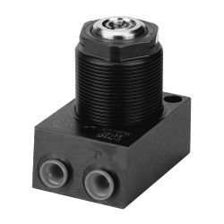
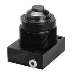
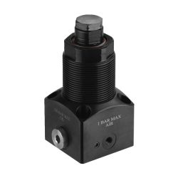
Support Element, block-type


Design:
Cylinder body from steel, burnished. Support pin case hardened and ground. Internal locking sleeve system Kostyrka. Special wiper prevents contamination. Support pin with internal thread. Home position retracted or extended, depending on function. Internal parts from stainless steel. Oil supply via threaded connection or oil channel in the fixture body.
Application:
Support element no. 6961F-**: Plunger extended, spring adjustable contact force.
These spring or pneumatic advancing hydraulic support elements provide additional support to avoid vibration or deflection during machining. Even large workpiece tolerances can be compensated (castings). Fitted directly below a clamping point they prevent distortion of the workpiece. The support elements can be matched with clamping cylinders of same nominal size into one circuit. To prevent the support plunger from possible slackening during a clamping procedure, it is advisible to connect a sequence valve (no. 6918-2) to control the support elements. Due to this fact, the support element is locked before the clamping procedure can be activated (fig. 1). Being used as an additional support to prevent from bending and vibration, the element should be preceded by a sequence valve (no. 6918-2) in order to ensure supporting before clamping. In case the clamping force is higher than the support force, the clamping force has to be reduced by using a pressure recluding valve no. 6917 (fig. 2).
Features:
High resilience due to high operating pressure, matched to the forces of the clamping cylinder row. Smooth contacting of the workpiece by adjustable spring. Universal use in each position.
Easy attachment of thrust pieces in the piston rod thread.
Note:
For spring advanced types, there is risk of sucking in coolant! To avoid this, a breather hose has to be connected to the pneumatic port and moved to a protected area. Support pin must be protected against the entry of dirt and splash water by fitting a set screw or plug. The support elements must be properly vented! The vent port must always be on top. Failure to do so can cause destruction of the clamping element by the escaping diesel.
The supporting force should be matched to the clamping force in order to absorb machining forces.
The supporting force should always be at least twice as high as the clamping force.
*Article No. 6961F-**: Contact force F1 dependent on spring pretensioning and setting travel.
| Order no. | 65276 |
|---|---|
| Max. operating pressure [bar] | 400 |
| Max. support force [kN] | 20 |
| Stroke [mm] | 10 |
| Mounting | Block |
| Positioning | Spring |
| Weight [g] | 3100 |
If you are missing a download, please write to us using our contact form.

| Area | Language | File name | Type | File size |
|---|
For general downloads, such as catalogs and brochures, please click here.
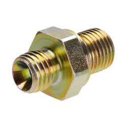
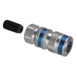
- Quick Disconnect Coupler Nr. 69021 Sleeve with external thread, max. operating pressure 1000 bar, nominal size 2,5
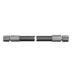
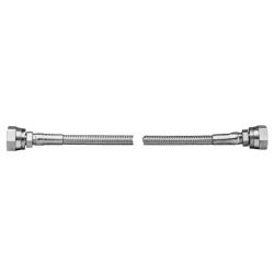
- High Pressure Hose with steel-wire interlace Nr. 68551 For thread connection, max. operating pressure 500 bar, length 300 mm
- Support Element, base-flange-mounting Nr. 66894 Max. support force 33,4 kN, stroke 12,5 mm, spring advanced
- Support Element, base-flange-mounting Nr. 66688 Max. support force 33,4 kN, stroke 12,5 mm, air advanced
- Support Element, base-flange-mounting Nr. 325878 Max. support force 17 kN, stroke 12,5 mm, spring advanced, hydraulic advanced
- Support Element, base-flange-mounting Nr. 567071 Max. support force 35,6 kN, stroke 15,8 mm, spring advanced, hydraulic advanced
- Support Element, cartridge flange Nr. 567066 Max. support force 35,6 kN, stroke 15,8 mm, spring advanced, hydraulic advanced, thread M45x1,5

- Support Element, cartridge flange Nr. 165241 Max. support force 17 kN, stroke 12,5 mm, spring advanced, hydraulic advanced, thread M60x1,5